OP-AMP Block Diagram
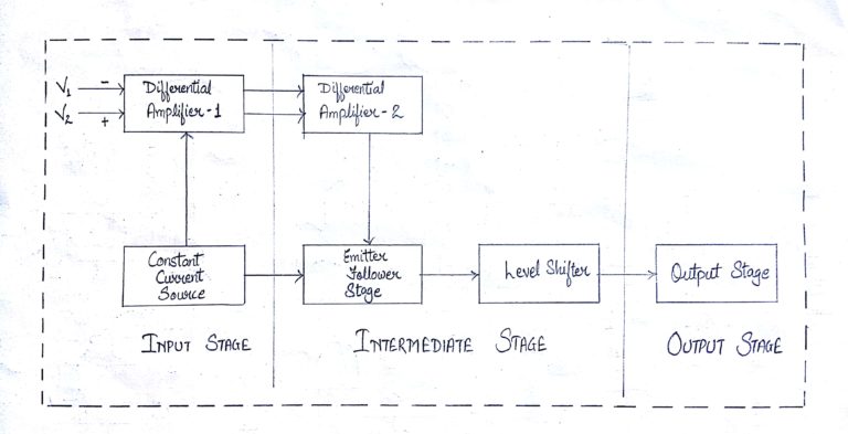
Input Stage
This is the first stage and has the following characteristics.
High CMRR (Common Mode Rejection Ratio)
High input impedance
Wide band width
Low (DC) input offset
These are some significant characteristics for the performance of the operational amplifier. This stage consists of a differential amplifier stage and a transistor is biased so that it acts as a constant current source. The constant current source greatly increases the CMR of the differential amplifier.
Following are the two inputs to the differential amplifier −
V1 = Non inverting input
V2 = Inverting input
Intermediate Stage
This is the second stage and designed to get better voltage and current gains. The current gain is required to supply sufficient current to drive the output stage, where most of the operational amplifier power is generated. This stage consists of one or more differential amplifiers followed by an emitter follower and a DC level shifting stage. Level shifting circuit enables an amplifier to have two differential inputs with a single output.
| Vout = +ve | when V1 > V2 |
| Vout = -ve | when V2 < V1 |
| Vout = 0 | when V1 = V2 |
Output Stage
This is the last stage of the op-amp and is designed to have low output impedance. This provides the needed current to drive the load. More or less current will be drawn from the output stage as and when the load varies. Therefore, it is essential that the previous stage operates without being influenced by the output load. This requirement is met by designing this stage so as to have high input impedance and high current gain, however with low output impedance.
The operational amplifier has two inputs: Non-inverting input and Inverting input.
An Operational Amplifier is basically a three-terminal device which consists of two high impedance inputs, one called the Inverting Input, marked with a negative or “minus” sign, ( – ) and the other one called the Non-inverting Input, marked with a positive or “plus” sign ( + ). And the third one is the output terminal.
Inverting Input:
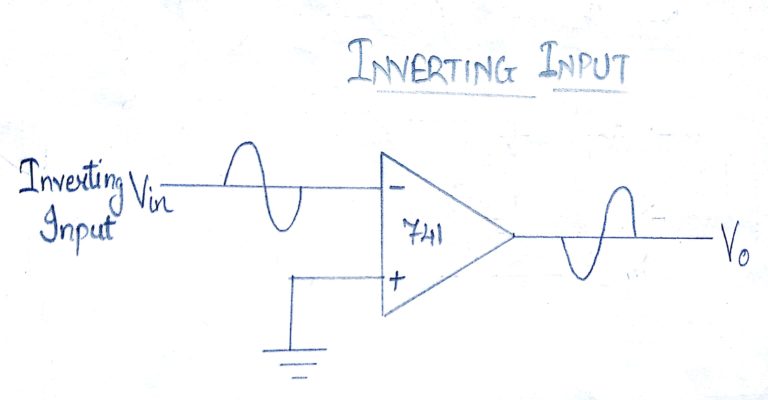
In this configuration, the input voltage signal, ( VIN ) is applied directly to the inverting ( – ) input terminal which means that the output gain of the amplifier becomes “Negative in value.
A signal which is applied at the inverting input terminal is amplified, however the output signal is out of phase with the input signal by 180 degrees.
Non Inverting Input:
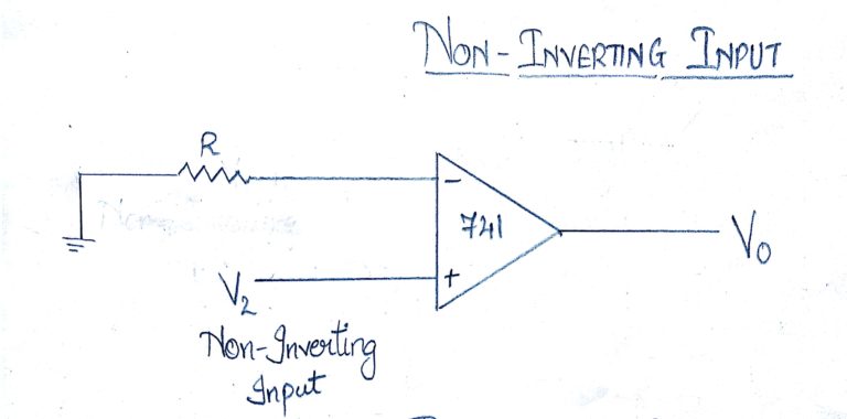
In this configuration, the input voltage signal, ( VIN ) is applied directly to the non-inverting ( + ) input terminal which means that the output gain of the amplifier becomes “Positive” in value.
A signal applied at the non–inverting input terminal is amplified and the output signal is in phase with the input signal.
The op-amp can be connected in large number of circuits to provide various operating characteristics.
The output voltage signal from an Operational Amplifier is the difference between the signals being applied to its two individual inputs. In other words, an op-amps output signal is the difference between the two input signals as the input stage of an Operational Amplifier is in fact a differential amplifier.
The Voltage Gain (AV) of the operational amplifier can be found using the following formula:
Av = Vout/Vin