Auto Parking Status
The project is designed to develop an Automatic system for giving the parking status for the given parking slot . This system indicates no entry to a vehicle to park when the parking area is occupied. Nowadays in many major cities of the world, there is a severe problem for car parking systems. There are many lanes for car parking, so to park a car one has to look for all the lanes. Moreover there is a lot of men labor involved for this process for which there is lot of investment. So the need is to develop a system which indicates directly which parking slot is vacant in any lane from a far distance.
The idea behind taking up this project was to make the students understand how to interface a display device to Arduino. Also to know more about the LCD and its working in 4 bit mode
List Of Components:
1. Arduino Uno R3
2. Arduino Cable
3. Male to Male Jumpers
4. Male To Female Jumpers
5. Buzzer
6. Ultrasonic Sensor HC SR-04
7. LCD Display
8. Breadboard
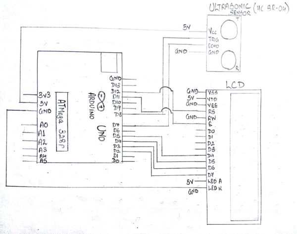
Steps For Connections:
Make separate common connections line for VCC and GND.
For Ultrasonic sensor:
Connect the Vcc pin to the common Vcc line.
Connect the GND pin to the common GND line.
Connect the trig pin to the digital pin – 8 of the Arduino.
Connect the echo pin to the digital pin – 7 of the Arduino.
For LCD Display:
Connect the VSS pin to the common GND line.
Connect the VDD pin to the common Vcc line.
Connect the VEE pin to the common GND line.
Connect the RS pin to the digital pin – 12 of the Arduino.
Connect the RW pin to the common GND line.
Connect the E pin to the digital pin – 11 of the Arduino.
Connect the D4 pin to the digital pin – 5 of the Arduino.
Connect the D5 pin to the digital pin – 4 of the Arduino.
Connect the D6 pin to the digital pin – 3 of the Arduino.
Connect the D7 pin to the digital pin – 2 of the Arduino.
Connect the LED A(Anode, or LED+) pin to the common Vcc line.
Connect the LED K(Cathode, or LED-) pin to the common GND line.
Connect the two common Vcc and GND lines to the Vcc(+5V) and GND of the Arduino using two jumpers.
About Code:

Include the LiquidCrystal library, to enable the various LCD functions.
This library is provided by Arduino by default.
Declare the variables used to indicate the arduino pins to be connected to the pins of Ultrasonic Sensor (Trigger and echo).
Declare the variables to be used as a storing element.
Declare the variables used to indicate the LCD pins to be connected to the Arduino and then assign those variables in the LCD function.
We are using the lcd in 4 bit mode, so we have declared only 4 data pins i.e. from D4-D7.
void setup
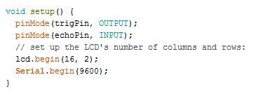
Define the Pin Mode as “INPUT” of the echo pin of Ultrasonic Sensor as it would give the values of the echo duration to which the controller will accept, process and provide an output.
Define the Pin Mode as “OUTPUT” of the trigger pin as the microcontroller would send pulses which would be detected by the Echo pin.
lcd.begin is used to initialize the lcd.
To check the distance between the object and the sensor, Serial Communication is used which would display the values on the Arduino’s Serial Monitor.
The baud rate is set to 9600 to start the serial communication.
-void loop:
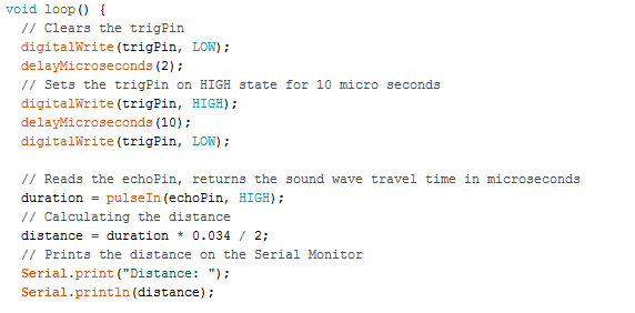
Trig pin requires 10 micro second pulse to transmit.
Now, the echo pin is checked for the amount of time it receives back the pulse transmitted by the trigger pin, indicating the detection of an object.
Distance is calcuted by using the general formula using time and speed of sound.
Here, Distance is measured in cm.
The value of Distance obtained is then displayed on the Serial Monitor using Serial.print
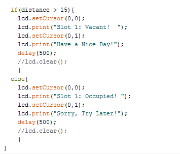
An if else loop is made to satisfy a condition and display the output on the LCD.
Here, if the distance is more than 15cm, The slot will be shown as Vacant else it will be displayed as Occupied.
lcd.setCursor function is used to indicate the position of the cursor from where the text will begin to display.
Here, when lcd.setCursor(0,0) it means 1st column and 1st row whereas (0,1) represents 1st column and 2nd row.
lcd.print function is used to display the desired text.
Steps for Compiling Program:
1. Click on ‘Sketch’ on Menu bar.
2. Select ‘Verify/Compile’.
(or)
Press Ctrl + R
(or)
Click on the first button just below the menu bar. (Button with a tick)
Steps for Uploading Program:
1. Click on ‘Tools’ on the Menu Bar.
2. Go to ‘Board’ and select whichever Arduino you are using. Here, Arduino/Genuino Uno.
3. Go to ‘Port’ and select the COM Port in which you have connected your Arduino Uno. You can check out your COM Port by going to Device Manager>PORTS(COM & LPT)
4. Go to Programmer and select ‘AVRISP’.
5. Now click on ‘Sketch’ on Menu Bar.
6. Select Upload.
(or)
Press Ctrl + U
(or)
Click on the button next to the ‘verify/compile’ button below the Menu Bar. (Button with a right arrow).
If you are using an USBasp cable instead of Arduino Cable, then Choose USBasp in the Programmer options.
And then go to ‘Sketch’ and select ‘Upload using Programmer’ (or) press Ctrl+Shift+U.