Active High Filter
The Principle of operation of the Active high pass Filter is same as the passive high pass filter i.e.the High Pass Filter as the name suggests the circuit allows only the frequency of the above the cut off frequency of the circuit and other all frequencies below the cut off frequency are rejected. The Difference this time is that it uses the active components for the amplification and gain control due to the the use of Active Components in the filter and the active component used over here is Op-amp. As Op-amp has its own frequency response so it is not possible for it to provide gain to all the frequencies above the cut-off i.e. it won’t provide gain to infinite frequency compared to passive filter. A first-order (single-pole) Active High Pass Filter as its name implies, attenuates low frequencies and passes high frequency signals. It consists simply of a passive filter section followed by a non-inverting operational amplifier. The frequency response of the circuit is the same as that of the passive filter, except that the amplitude of the signal is increased by the gain of the amplifier and for a non-inverting amplifier the value of the pass band voltage gain is given as 1 + R2/R1, the same as for the low pass filter circuit.
This first-order high pass filter, consists simply of a passive filter followed by a non-inverting amplifier. The frequency response of the circuit is the same as that of the passive filter but till the operating frequency range of the Op-amp as it exceeds the operating frequency the gain provided to the frequencies decrease and that the amplitude of the signal is increased by the gain of the amplifier. For a non-inverting amplifier circuit, the voltage gain for the filter is dependent on the feedback resistor ( R2 ) divided by its corresponding input resistor ( R1 ) value and is given as:
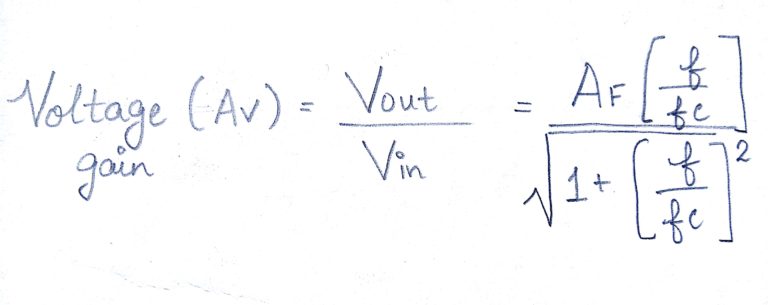
where :
AF = the Pass band Gain of the filter, ( 1 + R2/R1 )
ƒ = the Frequency of the Input Signal in Hertz, (Hz)
ƒc = the Cut-off Frequency in Hertz, (Hz)
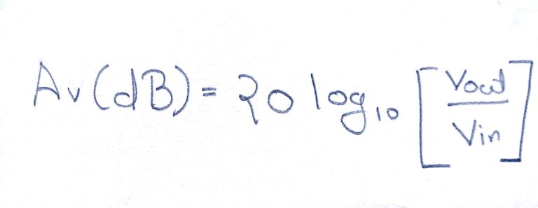
The Formula shown above is to calculate the gain provided in term of DB
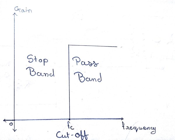
The Figure shown above is the Ideal characteristics of the Active High Pass Filter.
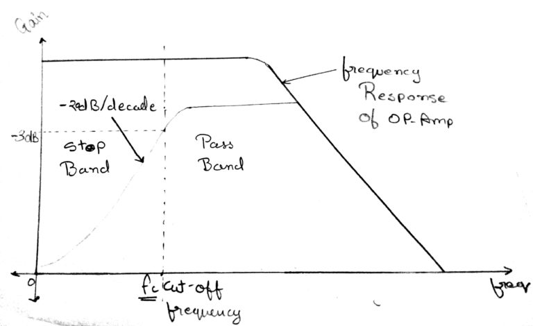
The Figure shown above is the Practical characteristics of the Active High Pass Filter.
Second Order High Pass Filter
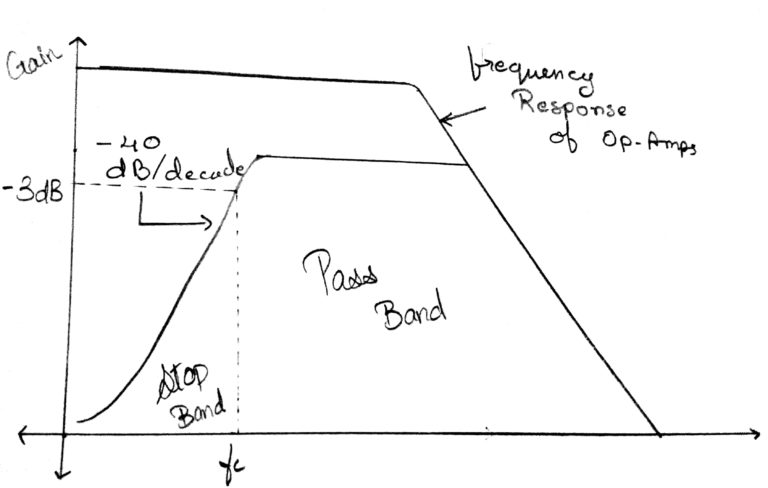
As with the passive filter, a first-order high pass active filter can be converted into a second-order high pass filter simply by using an additional RC network in the input path. The frequency response of the second-order high pass filter is identical to that of the first-order type except that the stop band roll-off will be twice the first-order filters at 40dB/decade i.e the double of the first order filter. Therefore, the design steps required of the second-order active high pass filter are the same.