Smart Lighting System
Ever thought of dimming lights in your house depending on the surrounding brightness. If yes then this is the project. In this project we will control the brightness of a LED depending on the surrounding brightness. Let’s take an example during the day time there is no need of light but as the time passes the need of light increases in accordance with the brightness in room. At that time there is need of light but not with full brightness we can work in dim light. The project helps us to do so. It just senses the brightness in the room that is using a light sensor and according to it brightness of the LED is controlled.
The Arduino is programmed such that the reading form the sensor is read by it and the according to the reading it gets from the sensor the brightness of the LED changes when there is sufficient light in the room the LED is off and as the brightness decreases in the room the brightness of the LED increases.
The main idea behind this project is to make students understand how light sensor can be interfaced with the arduino and also to make them learn about a new communication protocol called is I2C
Pre-requisites:
First download Arduino IDE from this website https://www.arduino.cc/en/main/software
Component List :
1. Arduino Uno R3
2. Arduino Cable
3. BH1750 Light Sensor
4. Jumper Wires,
5. Breadboard
6. LED
Connections :
Make the connections according to the Circuit Diagram
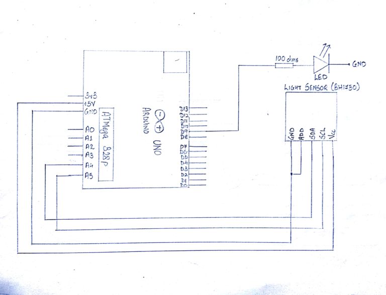
Steps For Connections:
1. Connect the Vcc of the BH1750 Light Sensor to the Vcc(+5V) of the Arduino Uno.
2. Short the GND and ADD (Address) pin of the BH1750 Light Sensor.
3. Connect the GND of the BH1750 Light Sensor to the GND of the Arduino Uno.
4. Connect the SDA pin of the BH1750 Light Sensor to the analog pin – ‘A4’ of the Arduino Uno.
5. Connect the SCL pin of the BH1750 Light Sensor to the analog pin – ‘A5’ of the Arduino Uno.
6. Connect the Cathode of the LED to GND.
7. Connect the Anode of the LED to one lead of the Resistor (100 ohms).
8. Connect the other lead of the Resistor (100 ohms) to the digital pin – ‘9’ of the Arduino Uno.
About Code:
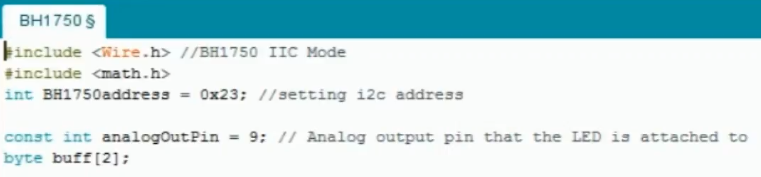
Include Wire.h library for I2C and include math.h for mathematical operations to be done in the code.
Initialize the address of BH1750 to 0x23
Declare the variable analogOutPin to pin number 9 for connecting the led
Declare a array of byte named as buff of the size 3 bytes (i.e 0,1,2 so written as byte buff[2])
void setup
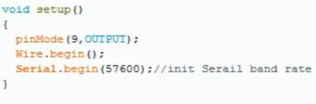
Define the Pin Mode as “OUTPUT” for LED i.e pin number 9
Initialize I2c with the command wire.begin()
Initialize the serial communication by Serial.begin(57600) . In this we have kept the baud rate as 57600 , The serial communication is used for the students , if they want to check the values coming from the light sensor . This step can also be ignored
BH1750_Init(int address) :
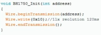
IN this function we have initalized our slave that is the light sensor.
BH1750_Read(int address) :
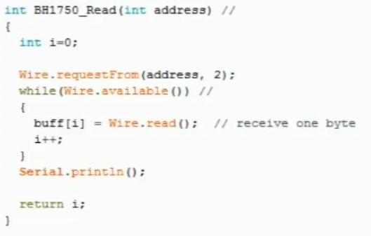
In this function we will take the input as the address of the light sensor . Here we have used a variable “i” which is initialized as 0 , then we request the data from the light sensor using the command Wire.requestFrom(address,2). This command Wire.requestFrom takes in 2 parameters , the first parameter is the address of the slave (In our case it is Light Sensor) and the second parameter is the quantity of data required in bytes (we have requested for 2 bytes ).
Now we have used a while function which will check the condition that the i2c communication is available or not , If it is available it will store the 1st byte of data to 0 position of the array buff . For having a pointer in an array we have used the variable i which was initialized as 0 above.
Once the data is stored in the 0th position , The value of i is incremented and made 1 and then the code again goes to while loop as we had requested 2 bytes of data . So the new data coming from the light sensor is stored in the first position of the buff as the value of i is now 1 .
After the 2 bytes of data , the code will not go to while loops as the condition will now won’t be satisfied.
void loop
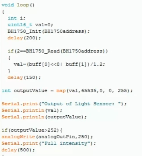
In this we have used a variable val which is initialized as 0 . This is a variable with data type int but with a storing capacity of 2 bytes i.e 16 bits .After that we will call the function of BH1750 _init for initialization and then a delay of 200ms is given .
After this we have used an if-else loop which will check, if the quantity of data requested in BH1750_read is equal to 2 only . If the condition is satisfied the data stored in the array of buff is copied into the 16 bit variable val. In this, the data stored at the 0 position of the buff is shifted by 8 positions to the left as it is the higher byte and the data stored at 1st position in the buff is the lower byte. The data stored in the val is divided by 1.2 for better calculations.
After this, the data stored in val which is basically a 16 bit number which means it can range till 2 to the power 16 that is 65535 (that is the max range of BH1750) is mapped down to 255 which is the max range of PWM in arduino uno . But in this we have used a reverse method . i.e instead of mapping 0 value of light sensor to 0 value of arduino and 65535 value of light sensor to 255 value of arduino, we have mapped 65535 of light sensor to 0 of arduino and 0 of light sensor to 255 of arduino. Though we can do in a normal way also after doing this either the students can check the value on serial monitor or directly jump to if else loop.
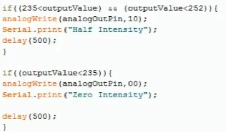
In if else loop different conditions are used and depending on that conditions different values are given to the led by using analog.Write . If there is complete darkness then max value is given to led so that it will illuminate the brightest and if there is sufficient light then 0 will be given to Led which will turn it off .
The students can also keep different stages depending on the data coming from the sensor . Here we have used 3 steps for our project
Alternative
Any Colour Sensor can be used.
Steps for Compiling Program:
1. Click on ‘Sketch’ on Menu bar.
2. Select ‘Verify/Compile’.
(or)
Press Ctrl + R
(or)
Click on the first button just below the menu bar. (Button with a tick)
Steps for Uploading Program:
1. Click on ‘Tools’ on the Menu Bar.
2. Go to ‘Board’ and select whichever Arduino you are using. Here, Arduino/Genuino Uno.
3. Go to ‘Port’ and select the COM Port in which you have connected your Arduino Uno. You can check out your COM Port by going to Device Manager>PORTS(COM & LPT)
4. Go to Programmer and select ‘AVRISP’.
5. Now click on ‘Sketch’ on Menu Bar.
6. Select Upload.
(or)
Press Ctrl + U
(or)
Click on the button next to the ‘verify/compile’ button below the Menu Bar. (Button with a right arrow).
If you are using an USBasp cable instead of Arduino Cable, then Choose USBasp in the Programmer options.
And then go to ‘Sketch’ and select ‘Upload using Programmer’ (or) press Ctrl+Shift+U.