OP-AMP Introduction
An Operational Amplifier, or op-amp is a voltage amplifying device designed to be used with external feedback components such as resistors and capacitors between its output and input terminals. It is a high-gain electronic voltage amplifier with a differential input and usually a single-ended output.
Operational amplifiers are linear devices that have all the properties required for nearly ideal DC amplification and are therefore used extensively in signal conditioning, filtering or to perform mathematical operations such as add, subtract, integration and differentiation.
In a linear operational amplifier, the output signal is the amplification factor, known as the amplifiers gain ( A ) multiplied by the value of the input signal and depending on the nature of the input and output signals.
The popularity of the op-amp as a building block in analog circuits is due to its versatility.
Due to negative feedback, the characteristics of an op-amp circuit, its gain, input and output impedance, bandwidth etc. are determined by external components and have little dependence on temperature coefficients or manufacturing variations in the op-amp itself.
5 Ideal characters of an Op Amp:
Open loop gain is the gain of the Op Amp without a positive or negative feedback. An ideal OP Amp should have an infinite open loop gain but typically it ranges between 20,000 and 2, 00000.
Input impedanceIt is the ratio of the input voltage to input current. It should be infinite without any leakage of current from the supply to the inputs. But there will be a few Pico ampere current leakages in most Op Amps.
Output impedanceThe ideal Op Amp should have zero output impedance without any internal resistance. So that it can supply full current to the load connected to the output.
Band widthThe ideal Op Amp should have an infinite frequency response so that it can amplify any frequency from DC signals to the highest AC frequencies. But most Op Amps have limited bandwidth.
OffsetThe output of the Op Amp should be zero when the voltage difference between the inputs is zero. But in most Op Amps, the output will not be zero when off but there will be a minute voltage from it.
OP-AMP Pin Configuration:
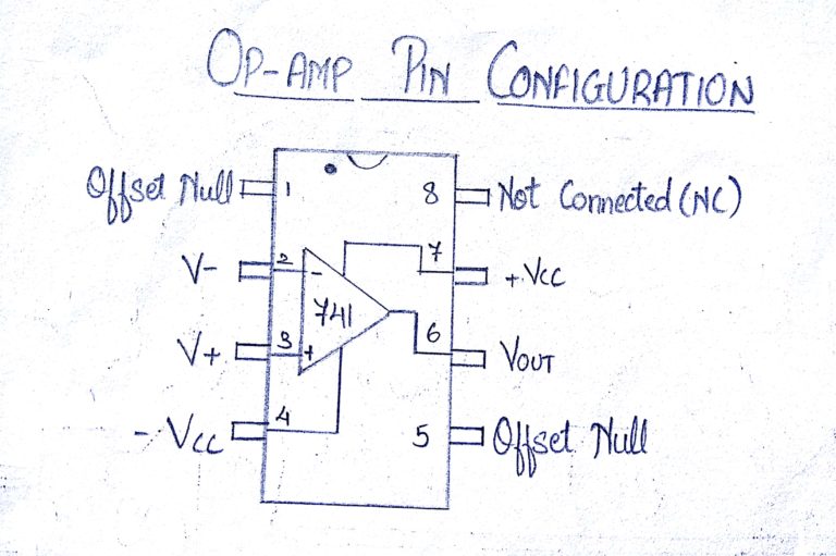
In a typical Op Amp there will be 8 pins. These are
Pin1 – Offset Null
Pin2 – Inverting input INV
Pin3 – Non inverting input Non-INV
Pin4 – Ground- Negative supply
Pin5 – Offset Null
Pin6 – Output
Pin7 – Positive supply
Pin8 – Strobe
4 types of gain in OP AMPs:
Voltage gain – Voltage in and voltage out
Current gain – Current in and Current out
Transconductance – Voltage in and Current out
Trans resistance – Current in and voltage out
An op amp has a wide range of uses and, depending how each pin is connected, the resulting circuit can be some of the following (this is by no means a comprehensive list):
Comparator
An Inverting Amplifier such as a summing amplifier
A Non-Inverting Amplifier such as a voltage follower
Difference Amplifier
Differentiator or Integrator
Filter
Peak Detector
Analog-to-Digital Converter
Oscillator
Negative Feedback:
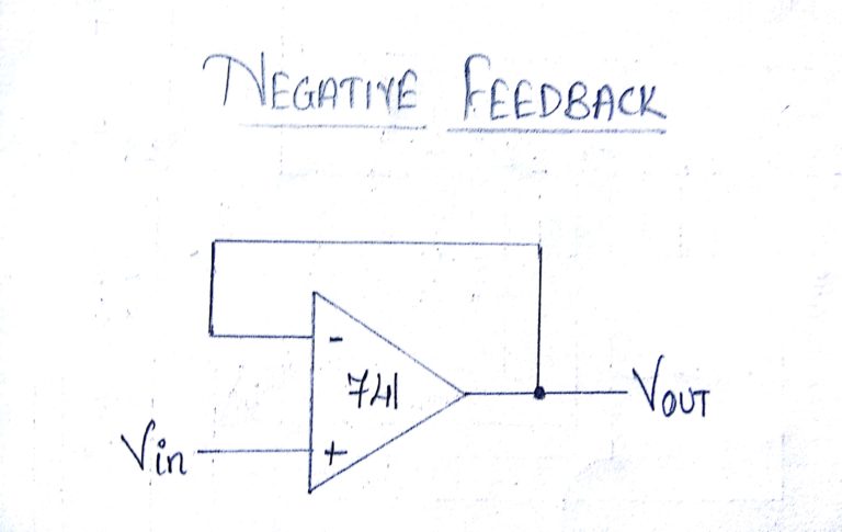
Here the output of the Op-Amp is connected to its Inverting ( – ) input, thus the output is fed back to the input so as to reach an equilibrium. Thus the input signal at the Non Inverting (+) input will be reflected at the output. The Op-amp with the negative feedback will drive its output to level necessary and hence the voltage difference between its inverting and non inverting inputs will be almost zero.
Positive Feedback:
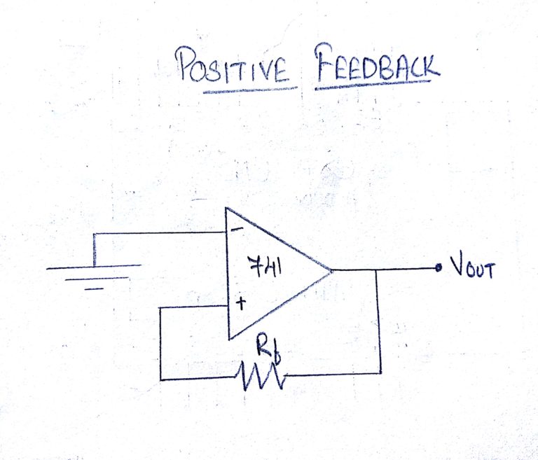
Here the output voltage is fed back to the Non inverting (+) input. The input signal is fed to the Inverting input. In positive feedback design, if the Inverting input is connected to ground, then the output voltage from the Op-amp will depends on the magnitude and polarity of voltage at the Non inverting input. When the input voltage is positive, then the output of the Op-Amp will be positive and this positive voltage will be fed to the Non inverting input resulting in a full positive output. If the input voltage is negative, then the condition will be reversed.