OP-AMP Applications
Inverting Amplifier
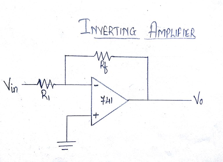
The following figure shows an inverting amplifier. The input signal is amplified and inverted. This is the most widely used constant-gain amplifier circuit.
OUTPUT
Vo = -Rf.Vin /R1
Voltage gain A = (-Rf /R1)
Non-Inverting Amplifier
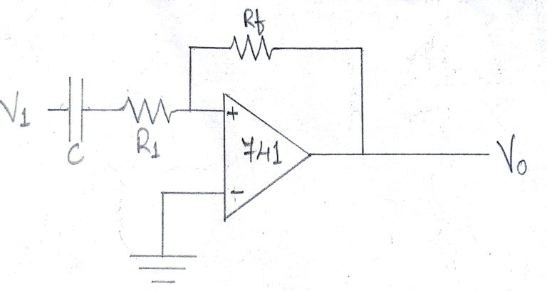
The following figure shows an op-amp circuit that works as a non-inverting amplifier or constant-gain multiplier and it has better frequency stability.
The input signal is amplified but it is not inverted.
OUTPUT
Vo = [(R1 + Rf) / R1] V1
Voltage gain A = (R1 + Rf) / R1
Voltage Follower
The circuit above is a voltage follower. Here it provides high input impedance, low output impedance .When the input voltage changes, the output and the inverting input will change equally.

Performance Characteristics
Common Mode Rejection Ratio
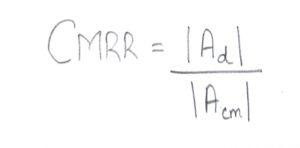
Common mode rejection ratio (CMRR) measures the amount of signal common to both inputs that is not amplified. It is desirable for the common mode gain to be very low, which corresponds with a very high CMRR.
The common mode rejection ratio is the ratio of the absolute value of differential gain to the absolute value of the common mode gain. The differential gain is typically half the intrinsic gain of the MOS transistor set by the manufacturer. Op amps with high output resistance will feature the best CMRR.
Power Supply Rejection Ratio
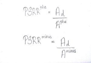
Power Supply Rejection Ratio or PSRR is the measure of the influence of the power supply ripple on the op amp output voltage. PSSR is important to MOSFET devices as they are usually on mixed-signal ICs where the digital switching in the circuit causes increased power supply ripple. The last thing you want in your design is to have that ripple amplified through your op amp.
The takeaway here is that to minimize the effects of ripple in power supplies, the Op Amp is required to have a large PSRR. So keep that in mind when looking at data sheets for any upcoming projects.
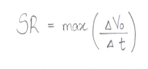
Slew Rate
Slew rate refers to the maximum rate of change possible at the output of an op amp. Most op amps are slew rate-limited, and that is calculated by taking the max of the derivative, with respect to time of the output voltage of the op amp.
Total Harmonic Distortion
The task of an audio amplifier is to take a small signal and amplify it without making any changes other than amplifying it. This is a difficult task because unwanted signals (i.e. ripple) may be amplified along with the desired signal. Any deviation from linearity is considered a distortion. Harmonic distortion is a common form of distortion in audio applications where the peaks of the output signal get “clipped.” The lower the percentage listed for THD the better, but after a certain point it is hardly perceptible to human ears.