Bistable Multivibrator
A Bistable Multivibrator has two stable states. The circuit stays in any one of the two stable states. It continues in that state, unless an external trigger pulse is given. This Multivibrator is also known as Flip-flop. This circuit is simply called as Binary.
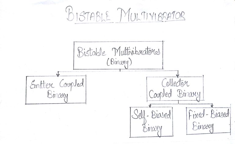
There are few types in Bistable Multivibrators. They are as shown in the following figure.
Construction of Bistable Multivibrator
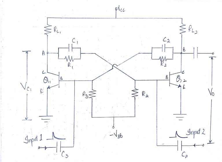
Two similar transistors Q1 and Q2 with load resistors RL1 and RL2 are connected in feedback to one another. The base resistors R3 and R4 are joined to a common source –VBB. The feedback resistors R1 and R2 are shunted by capacitors C1 and C2 known as Commutating Capacitors. The transistor Q1is given a trigger input at the base through the capacitor C3 and the transistor Q2 is given a trigger input at its base through the capacitor C4.
The capacitors C1 and C2 are also known as Speed-up Capacitors, as they reduce the transition time, which means the time taken for the transfer of conduction from one transistor to the other.
The following figure shows the circuit diagram of a self-biased Bistable Multivibrator.
Operation of Bistable Multivibrator
When the circuit is switched ON, due to some circuit imbalances as in Astable, one of the transistors, say Q1 gets switched ON, while the transistor Q2 gets switched OFF. This is a stable state of the Bistable Multivibrator.
By applying a negative trigger at the base of transistor Q1 or by applying a positive trigger pulse at the base of transistor Q2, this stable state is unaltered. So, let us understand this by considering a negative pulse at the base of transistor Q1. As a result, the collector voltage increases, which forward biases the transistor Q2. The collector current of Q2 as applied at the base of Q1, reverse biases Q1 and this cumulative action, makes the transistor Q1 OFF and transistor Q2 ON. This is another stable state of the Multivibrator.
Now, if this stable state has to be changed again, then either a negative trigger pulse at transistor Q2 or a positive trigger pulse at transistor Q1 is applied.
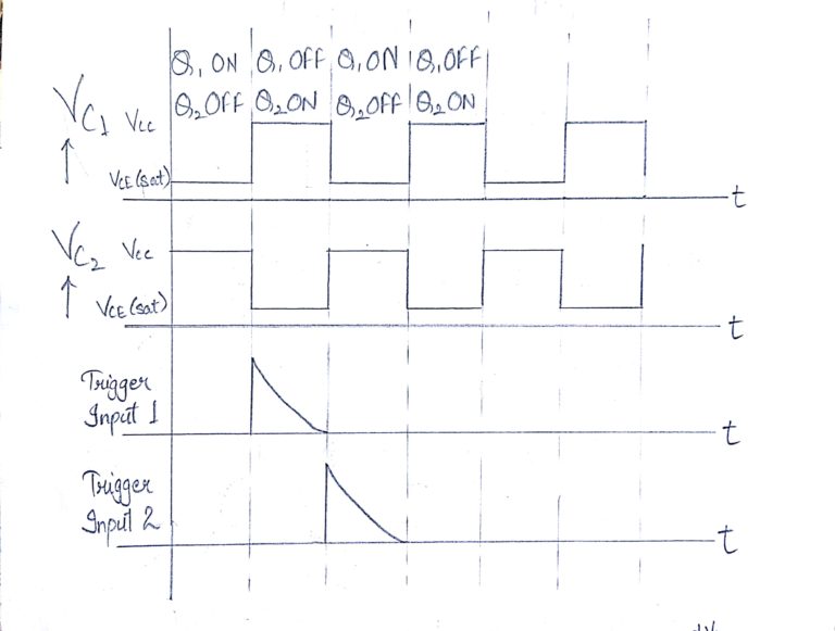
Output Waveforms
The output waveforms at the collectors of Q1 and Q2 along with the trigger inputs given at the bases of QW and Q2 are shown in the following figures.
FIXED BIASED BINARY CIRCUIT
Fixed-bias binary circuit is similar to an Astable Multivibrator but with a simple SPDT switch. Two transistors are connected in feedback with two resistors, having one collector connected to the base of the other. The figure below shows the circuit diagram of a fixed-bias binary.
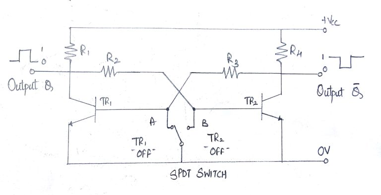
The Bistable Multivibrator circuit is stable in both states, either with one transistor “OFF” and the other “ON” or with the first transistor “ON” and the second “OFF”. Lets suppose that the switch is in the left position, position “A”. The base of transistor TR1 will be grounded and in its cut-off region producing an output at Q. That would mean that transistor TR2 is “ON” as its base is connected to Vcc through the series combination of resistors R1 and R2. As transistor TR2 is “ON” there will be zero output at Q, the opposite or inverse of Q.
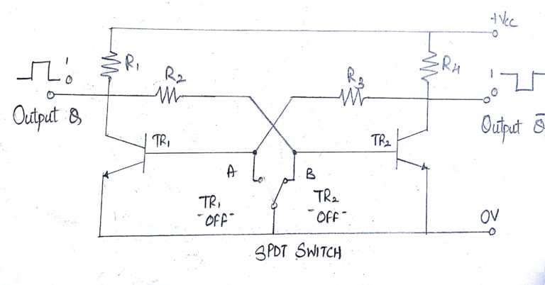
If the switch is now move to the right, position “B”, transistor TR2 will switch “OFF” and transistor TR1 will switch “ON” through the combination of resistors R3 and R4 resulting in an output at Q and zero output at Q the reverse of above. Then we can say that one stable state exists when transistor TR1 is “ON” and TR2 is “OFF”, switch position “A”, and another stable state exists when transistor TR1 is “OFF” and TR2 is “ON”, switch position “B”.
Then unlike the monostable multivibrator whose output is dependent upon the RC time constant of the feedback components used, the bistable multivibrators output is dependent upon the application of two individual trigger pulses, switch position “A” or position “B”.
So Bistable Multivibrators can produce a very short output pulse or a much longer rectangular shaped output whose leading edge rises in time with the externally applied trigger pulse and whose trailing edge is dependent upon a second trigger pulse as shown below.
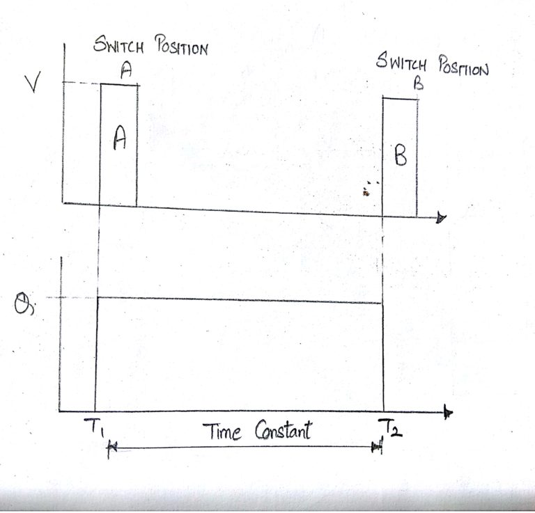
Bistable Multivibrator Waveform
Manually switching between the two stable states may produce a bistable multivibrator circuit but is not very practical.
Advantages
The advantages of using a Bistable Multivibrator are as follows −
Stores the previous output unless disturbed.
Circuit design is simple
Disadvantages
The drawbacks of a Bistable Multivibrator are as follows −
Two kinds of trigger pulses are required.
A bit costlier than other Multivibrators.
Applications
Bistable Multivibrators are used in applications such as pulse generation and digital operations like counting and storing of binary information.