SCR
A thyristor is a solid-state semiconductor device with four layers of alternating P- and N-type materials. It acts exclusively as a bistable switch, conducting when the gate receives a current trigger, and continuing to conduct while the voltage across the device is not reversed (forward-biased). A three-lead thyristor is designed to control the larger current of its two leads by combining that current with the smaller current of its other lead, known as its control lead.
Although we can use Transistors to switch tiny electrical currents on and off (that’s the basic principle behind computer memory), and transform small currents into somewhat larger ones (that’s how an amplifier works), transistors are not very useful when it comes to handling much bigger currents. Another drawback is that they turn off altogether as soon as the switching current is removed, which means they’re not so useful in devices such as alarms where you want a circuit to trigger and stay on indefinitely. For those sorts of jobs, we can turn to a somewhat similar electronic component called a thyristor.
Silicon Controlled Rectifier (SCR)
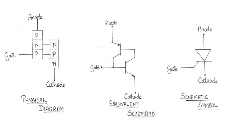
Silicon Controlled Rectifier (SCR) is an unidirectional semiconductor device made of silicon which can be used to provide a selected power to the load by switching it ON for variable amount of time. These devices are solid-state equivalent of thyratrons and are hence referred to as thyristors or thyrode transistors. In fact, SCR is a trade name of General Electric (GE) to the thyristor. Basically SCR is a three terminal, four-layer (hence of three junctions J1,
J2 and J3) semiconductor device consisting of alternate layers of p- and n-type material doping. the SCR with the layers pnpn which has the terminals Anode (A), Cathode (K) and the Gate (G). Further it is to be noted that the Gate terminal will generally be the p-layer nearer to the Cathode terminal.
Modes of operation
There are three modes of operation for an SCR depending upon the biasing given to it:
1. Forward blocking mode (off state)
2. Forward conduction mode (on state)
3. Reverse blocking mode (off state)
Forward blocking mode
In this mode of operation, the anode(+ve) is given a positive voltage while the cathode(-ve) is given a negative voltage, keeping the gate at zero(0) potential i.e. disconnected. In this case junction J1 and J3 are forward-biased, while J2 is reverse-biased, due to which only a small leakage current exists from the anode to the cathode until the applied voltage reaches its breakover value, at which J2 undergoes avalanche breakdown, and at this breakover voltage it starts conducting, but below breakover voltage it offers very high resistance to the current and is said to be in the off state.
Forward conduction mode
SCR can be brought from blocking mode to conduction mode in two ways: either by increasing the voltage across anode to cathode beyond breakover voltage or by applying positive pulse at gate. Once SCR starts conducting, no more gate voltage is required to maintain it in the on state.
The more the gate voltage, the faster the SCR starts conducting. There are two ways to turn it off: 1. Reduce the current through it below a minimum value called the holding current and 2. With the gate turned off, short out the anode and cathode momentarily with a push-button switch or transistor across the junction.
Reverse blocking mode
SCRs are available with reverse blocking capability, which adds to the forward voltage drop because of the need to have a long, low-doped P1 region. (If one cannot determine which region is P1, a labeled diagram of layers and junctions can help). Usually, the reverse blocking voltage rating and forward blocking voltage rating are the same. The typical application for reverse blocking SCR is in current-source inverters.
SCRs incapable of blocking reverse voltage are known as asymmetrical SCR, abbreviated ASCR. They typically have a reverse breakdown rating in the tens of volts. ASCRs are used where either a reverse conducting diode is applied in parallel (for example, in voltage-source inverters) or where reverse voltage would never occur (for example, in switching power supplies or DC traction choppers).
Asymmetrical SCRs can be fabricated with a reverse conducting diode in the same package. These are known as RCTs, for reverse conducting thyristors.
Working of an SCR:
The end P-region is the anode, the end N-region is the cathode and the inner P-region is the gate. The anode to cathode is connected in series with the load circuit. Essentially the device is a switch. Ideally it remains off (voltage blocking state), or appears to have an infinite impedance until both the anode and gate terminals have suitable positive voltages with respect to the cathode terminal. The thyristor then switches on and current flows and continues to conduct without further gate signals. Ideally the thyristor has zero impedance in conduction state. For switching off or reverting to the blocking state, there must be no gate signal and the anode current must be reduced to zero. Current can flow only in one direction.
In absence of external bias voltages, the majority carrier in each layer diffuses until there is a built-in voltage that retards further diffusion. Some majority carriers have enough energy to cross the barrier caused by the retarding electric field at each junction. These carriers then become minority carriers and can recombine with majority carriers. Minority carriers in each layer can be accelerated across each junction by the fixed field, but because of absence of external circuit in this case the sum of majority and minority carrier currents must be zero.

Applications of SCR :
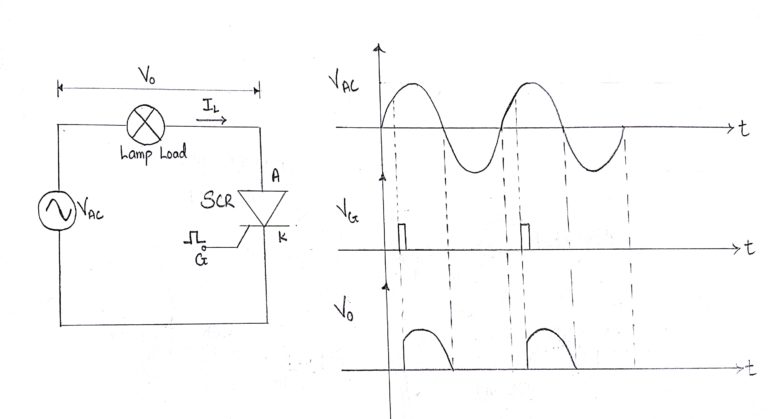
1. Phase Control of Signals
2. For switching of Electronic Devices
3. Triggering the ICs and different timing circuits.
4. Used as Controlled Rectifier