Active Low Pass Filter
The Principle of operation and frequency response of the Active low pass Filter is as the passive low pass filter i.e.the Low Pass Filter as the name suggests the circuit allows only the frequency of the till the cut off frequency of the circuit and other all frequencies above the cut off frequency are rejected. The only Difference this time is that it uses the active components for the amplification and gain control.
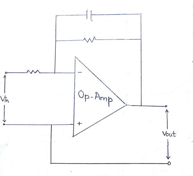
The simplest form of a low pass active filter is to connect an inverting or non-inverting amplifier, to the basic RC low pass filter circuit as shown.
The amplifier is configured as a voltage-follower (Buffer) giving it a DC gain of one, Av = +1 or unity gain as opposed to the previous passive RC filter which has a DC gain of less than unity.
The advantage of this configuration is that the op-amps high input impedance prevents excessive loading on the filters output while its low output impedance prevents the filters cut-off frequency point from being affected by changes in the impedance of the load. While this configuration provides good stability to the filter, its main disadvantage is that it has no voltage gain above one.
However, although the voltage gain is unity the power gain is very high as its output impedance is much lower than its input impedance. If a voltage gain greater than one is required we can use the following filter circuit.
Gain of a first-order low pass filter
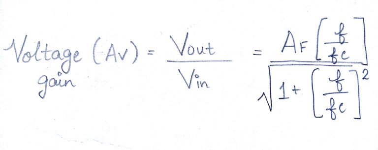
where
AF = the pass band gain of the filter, (1 + R2/R1)
ƒ = the frequency of the input signal in Hertz, (Hz)
ƒc = the cut-off frequency in Hertz, (Hz)
Thus, the Active Low Pass Filter has a constant gain AF from 0Hz to the high frequency cut-off point, ƒC. At ƒC the gain is 0.707AF, and after ƒC it decreases at a constant rate as the frequency increases. That is, when the frequency is increased tenfold (one decade), the voltage gain is divided by 10.
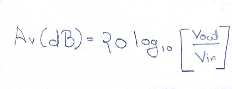
In other words, the gain decreases 20dB (= 20log 10) each time the frequency is increased by 10. Magnitude of Voltage Gain in (dB)
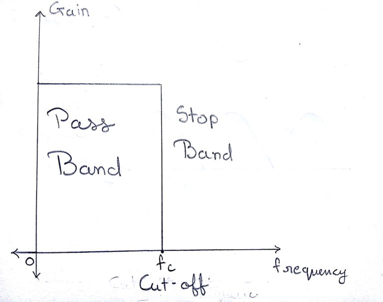
The Above figure shows the Ideal Characteristics of the First Order Active Low Pass Filter.
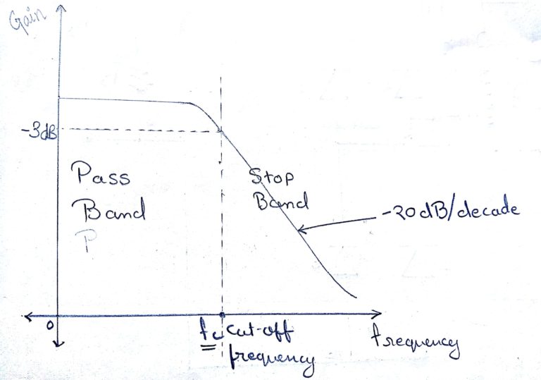
The Above figure shows the Ideal Characteristics of the First Order Active Low Pass Filter.
Second-order Low Pass Active Filter
As with the passive filter, a first-order low-pass active filter can be converted into a second-order low pass filter simply by using an additional RC network in the input path. The frequency response of the second-order low pass filter is identical to that of the first-order type except that the stop band roll-off will be twice the first-order filters at 40dB/decade
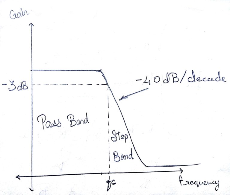
The figure shows the practical characteristics of the Active Low Pass Filter.