Wireless Notice Board
Today the world is moving from wire to wireless technology, so this is our first project where we will be displaying some data on a LCD Display via our Mobile phone using a Bluetooth Module.
This video will teach you how to configure a Bluetooth Module using Advanced technology i.e. AT Commands.
Requirements:
1. Arduino Uno R3
2. Arduino Cable
3. Bluetooth module HC-05
4. LCD display
5. Jumper wires
6. Breadboard
Connections:
Refer the schematics for the connections.
Please note: Remove the pins 0 and 1 while uploading the program or else there will be an error in uploading the code.
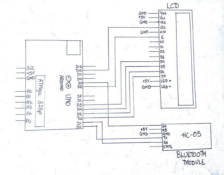
Steps For Connections:
Make separate common connections line for VCC and GND.
For Bluetooth HC-05:
Connect the Vcc to the common Vcc line.
Connect the GND to the common GND line.
Connect the TX pin of the Bluetooth to the RX of the Arduino uno i.e. digital pin 0.
Connect the RX pin of the Bluetooth to the TX of the Arduino uno i.e. digital pin 1.
Connect the Enable pin to the digital pin – 9 of the Arduino Uno.
For LCD Display:
Connect the VSS pin to the common GND line.
Connect the VDD pin to the common Vcc line.
Connect the VEE pin to the common GND line.
Connect the RS pin to the digital pin – 12 of the Arduino.
Connect the RW pin to the common GND line.
Connect the E pin to the digital pin – 8 of the Arduino.
Connect the D4 pin to the digital pin – 5 of the Arduino.
Connect the D5 pin to the digital pin – 4 of the Arduino.
Connect the D6 pin to the digital pin – 3 of the Arduino.
Connect the D7 pin to the digital pin – 2 of the Arduino.
Connect the LED A(Anode, or LED+) pin to the common Vcc line.
Connect the LED K(Cathode, or LED-) pin to the common GND line.
Connect the two common Vcc and GND lines to the Vcc(+5V) and GND of the Arduino using two jumpers.
About Code:
AT commands:
In this project we have used AT commands to configure our bluetooth module.Before starting the configuration process , please make a note that the VCC of the bluetooth should be connected in the last and while doing so the button on the bluetooth module should be pressed. This process will make the bluetooth module in AT mode that is in configuration mode.
You can check whether the module is in the AT mode or not by the led on the module. If the led is blinking very fast , then it means that the Module is still in the communication mode and not in the AT mode and if the led is blinking slowly and we can say that the bluetooth is in the AT mode.
Once it is in the AT mode , You need to write a basic program for serial read and serial write for sending and reading the AT commands through the serial monitor. Also keep the baud rate as 38400 while using the module in AT mode asit is the default for HC-05.You need to use Software Serial for this purpose.
The important AT commands for our project are:
AT – To test whether the bluetooth is working or not
Reply: OK
AT+PSWD? – To get the passkey which we require hen we pair our cellphones to the module
Reply: +PSWD:xxxx (In our case the passkey was 1234)
AT+UART = 9600,0,0 – To set the communication baud rate as 9600 with 0 stop bit and 0 parity bit.This is the default communication speed of HC-05
Reply: OK
After initialization turn off the power and again turn On it and now the bluetooth module will be in the Communication mode.
Arduino Code:
#Declaration:
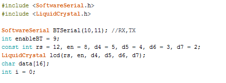
We have included LiquidCrystal library for the lcd. We use pin 9 for the enable pin of the bluetooth module. THen we have initialized pin 12,8,5,4,3,2 for the LCD.Declare an array called data with size 16 and a variable called i as 0 for pointing the location of the array.
#Void setup
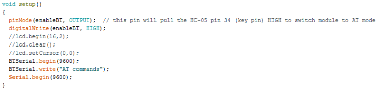
Set the enable pin as the output and make it high to enable the bluetooth module .Initialize the lcd and also clear it if it has any earlier data and the cursor on the leftmost part for the 1st line by using the command setCursor .Initialize the serial communication with the baud rate 9600
#Void loop
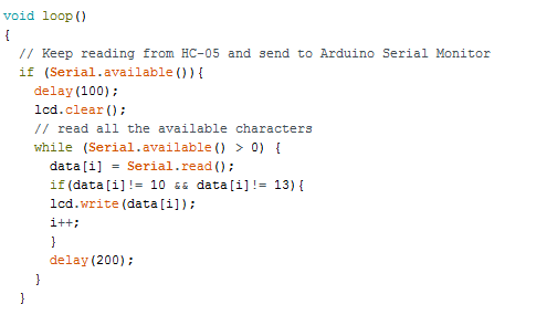
In loop we have used a if loop for checking whether the serial communication is available or not and if it is available then a delay is given and if there is any data on the lcd ,then it is cleared.Then we have used a while loop which has the argument as serial available .
If the condition is true ,then the code will enter the loop and read the first byte of data and store it in the first location of the array.After doing so it will check whether the last incoming data was not containing ASCII code 10 or 13 which is for line feed and carriage return which are basically ASCII control characters and comes when we send enter.If you don’t use the loop and use lcd.write outside,still it will display the data but along with data it will show 2 garbage values which will be carrier return and line so to avoid that we have used this loop. And lastly we have incremented the value of i for storing the data to the next location in the array.
Steps for Compiling Program:
1. Click on ‘Sketch’ on Menu bar.
2. Select ‘Verify/Compile’.
(or)
Press Ctrl + R
(or)
Click on the first button just below the menu bar. (Button with a tick)
Steps for Uploading Program:
1. Click on ‘Tools’ on the Menu Bar.
2. Go to ‘Board’ and select whichever Arduino you are using. Here, Arduino/Genuino Uno.
3. Go to ‘Port’ and select the COM Port in which you have connected your Arduino Uno. You can check out your COM Port by going to Device Manager>PORTS(COM & LPT)
4. Go to Programmer and select ‘AVRISP’.
5. Now click on ‘Sketch’ on Menu Bar.
6. Select Upload.
(or)
Press Ctrl + U
(or)
Click on the button next to the ‘verify/compile’ button below the Menu Bar. (Button with a right arrow).
If you are using an USBasp cable instead of Arduino Cable, then Choose USBasp in the Programmer options.
And then go to ‘Sketch’ and select ‘Upload using Programmer’ (or) press Ctrl+Shift+U.