Smart Classroom
The system is designed for optimum energy usage and is very beneficial in case if we want to count the number of students entering or leaving the classroom thereby helps in collecting data by counting the number of people.This is done by simply incrementing the counter.
The system uses InfraRed Sensor pairs in order to fulfill this purpose and thus saves a large amount of energy. Each pair consists of 2 sensor pairs placed at a certain distance from one another in the opposite direction. The IR transmitter is used to transmit IR rays straight to the receiver which receives the input and feeds this to an 8051 Microcontroller.
As soon as a person enters the area where the system is placed, it is detected by the IR sensor module and this info is fed to the microcontroller. The microcontroller process this input received. At this time the system also counts the number of people present and increments a counter on each arrival, this count is displayed on a 7 segment display. This helps the teacher in taking while taking attendance. The other IR module helps in counting the number of students that leave the class. As soon as the student exists the class IR module passes the signal to the microcontroller and decrements the count of students. The count is then displayed on the 7 Segment Display.
List Of Components:
1. Arduino Uno R3
2. Arduino Cable
3. Male to Male Jumpers
4. Male To Female Jumpers
5. 7- segment display (common cathode is used in our project)
6. Resistors of 220 ohm
7. IR Modules
8. Breadboard
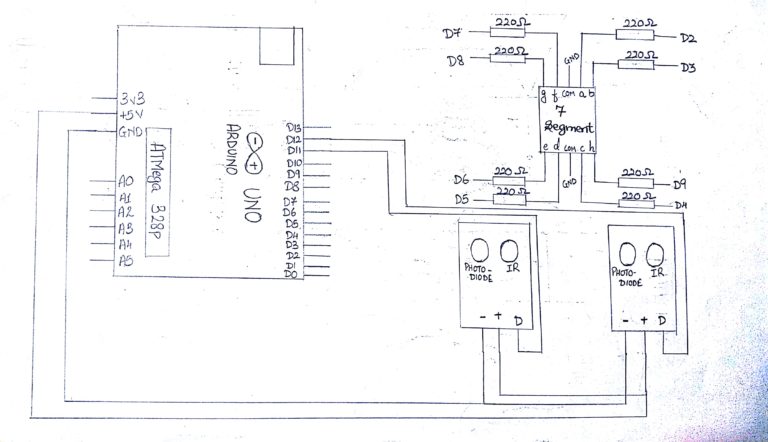
Steps For Connections:
Make separate common connections line for VCC and GND.
For IR modules:
Connect the Vcc of both the IRs to the common Vcc line.
Connect the GND of both the IRs to the common GND line.
Connect the Data pin (D) of the 1st IR (IR enter) to the digital pin – 12 of the Arduino.
Connect the Data pin (D) of the 2nd IR (IR exit) to the digital pin – 13 of the Arduino.
For the 7-segment Display:
Connect the ‘a’ pin to the digital pin – 2 of the Arduino.
Connect the ‘b’ pin to the digital pin – 3 of the Arduino.
Connect the ‘c’ pin to the digital pin – 4 of the Arduino.
Connect the ‘d’ pin to the digital pin – 5 of the Arduino.
Connect the ‘e’ pin to the digital pin – 6 of the Arduino.
Connect the ‘f’ pin to the digital pin – 7 of the Arduino.
Connect the ‘g’ pin to the digital pin – 8 of the Arduino.
Connect the ‘h’ pin to the digital pin – 9 of the Arduino.
Connect the ‘COM’ pin to the common GND line.
Connect the two common Vcc and GND lines to the Vcc(+5V) and GND of the Arduino using two jumpers
About Code:
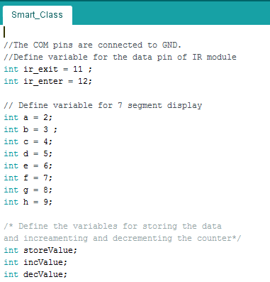
Declare the variables used to indicate the arduino pins to be connected to the pins of IR module that is the data pins of the IR module which are named as ir_exit and ir_enter in the code.
Declare the variables to be used for 7 segment such as its 8 pins (a,b,c,d,e,f,g,h ) .
Declare the variables used to store the data and for incrementing and decrementing the counter
The COMMON pins of the 7 segment Display are connected directly to Ground.
There are different functions which are made for displaying the number
Like -Void one
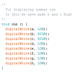
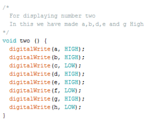
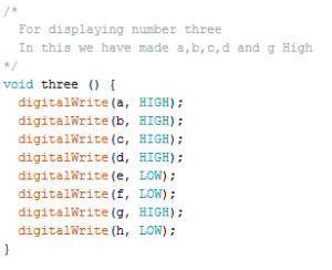
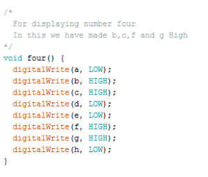
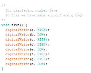
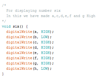
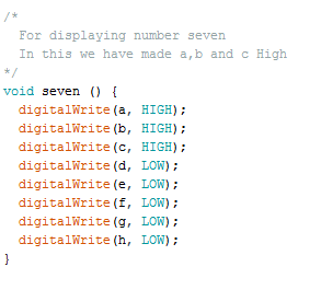
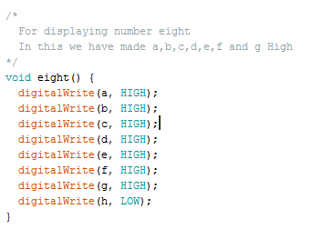
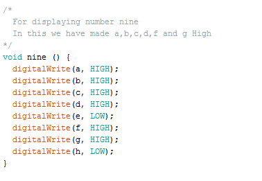
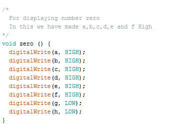
In this function we make 8 pins of 7 segments High or low depending on the number to be displayed.
Similarly the other functions like two,three and so on are created for displaying the given number
void setup
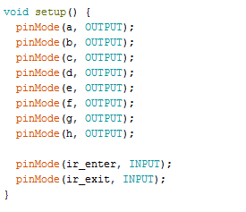
*Define the Pin Mode as “INPUT” of the data pin of IR Sensor module that are ir_enter and ir_exit as it would give the values High or Low .
*Define the Pin Mode as “OUTPUT” of the pins of the 7 segment display
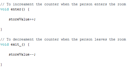
Void enter :
This function will increment the variable storeValue for the count
Void exit :
This function will decrement the variable storeValue for the count
-void loop:
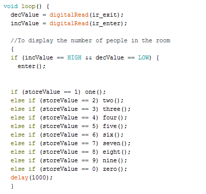
Two variables decValue and incValue are used to read the values coming from ir_enter and ir_exit .Here we have used digitalRead as the IR modules are connected the digital pins.
After storing the data coming from the IR module ,we have used a if else loop where if the ir_enter is cut that is incValue variable gets High then it should understand that the person has entered the room and then enter function is called and the counter is incremented
In this, if else loop we have used a nested if loop for calling the function for displaying the number.
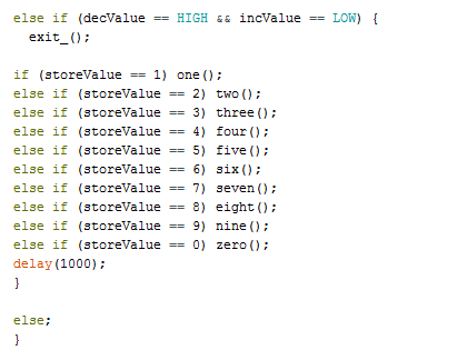
Similarly for else if loop if the ir_exit is cut that is decValue variable gets High then it should understand that the person has left the room and then exit function is called and the counter is decremented.
In this ,if else loop we have used a nested if loop for calling the function for displaying the number.
Steps for Compiling Program:
1. Click on ‘Sketch’ on Menu bar.
2. Select ‘Verify/Compile’.
(or)
Press Ctrl + R
(or)
Click on the first button just below the menu bar. (Button with a tick)
Steps for Uploading Program:
1. Click on ‘Tools’ on the Menu Bar.
2. Go to ‘Board’ and select whichever Arduino you are using. Here, Arduino/Genuino Uno.
3. Go to ‘Port’ and select the COM Port in which you have connected your Arduino Uno. You can check out your COM Port by going to Device Manager>PORTS(COM & LPT)
4. Go to Programmer and select ‘AVRISP’.
5. Now click on ‘Sketch’ on Menu Bar.
6. Select Upload.
(or)
Press Ctrl + U
(or)
Click on the button next to the ‘verify/compile’ button below the Menu Bar. (Button with a right arrow).
If you are using an USBasp cable instead of Arduino Cable, then Choose USBasp in the Programmer options.
And then go to ‘Sketch’ and select ‘Upload using Programmer’ (or) press Ctrl+Shift+U.