DIAC
A DIAC is a full-wave or bi-directional semiconductor switch that can be turned on in both forward and reverse polarities.
The name DIAC comes from the words DIode AC switch. The DIAC is an electronics component that is widely used to assist even triggering of a TRIAC when used in AC switches and as a result they are often found in light dimmers such as those used in domestic lighting. These electronic components are also widely used in starter circuits for fluorescent lamps.
The symbols of the diac has two arrows in both directions, which means that it conduct for either polarity of the supply voltage. A diac don’t have a controlling terminal as a gate in case of thyristor devices.
DIAC Construction
The construction of diac looks like a transistor; however, there are several differences between these two. Some of these are
The doping concentrations in all the layers in diac are identical, whereas the transistor has a highly doped emitter, lightly doped collector and moderately doped base.
Transistor is a three terminal device, whereas the diac is a two terminal device.
The three regions in diac are equal in size.
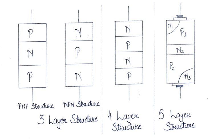
The diac can be fabricated into three, four or five layer structure. A three layer structure is more commonly used than other structure. The three layer diac can be constructed in either PNP or NPN structure. In PNP form, two terminals are connected to the outer silicon P-regions separated by N region. This structure is same as PNP transistor with no base connection.
Characteristics of DIAC
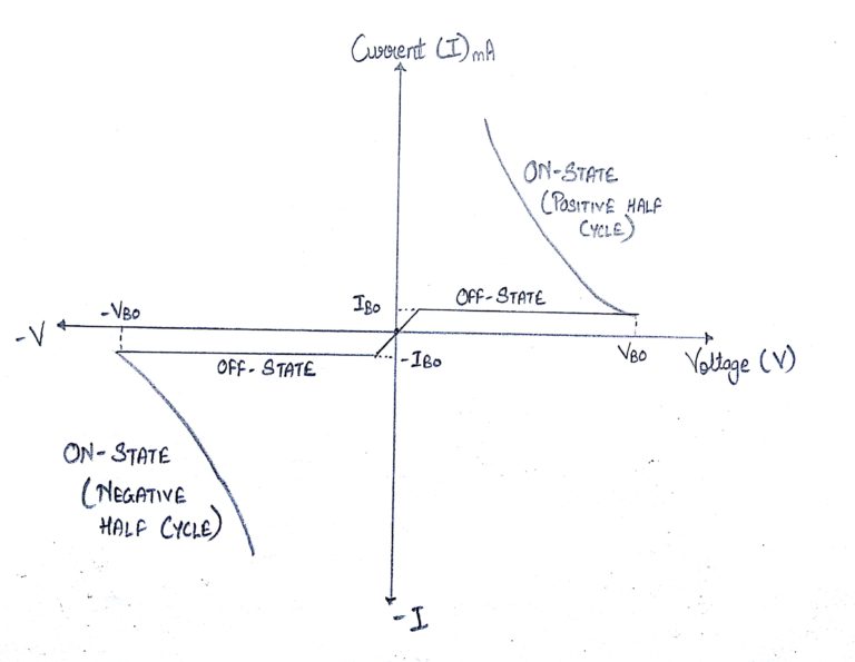
V-I (Volt-ampere) characteristic of a diac is shown in figure. Its looks like a letter Z due to symmetrical switching characteristics for each polarity of the applied voltage.
The diac performs like an open-circuit until its switching is exceeded. At that position the diac performs until its current decreases toward zero. Because of its abnormal construction, doesn’t switch sharply into a low voltage condition at a low current level like the triac or SCR, once it goes into transmission, the diac preserves an almost continuous –Ve resistance characteristic, that means, voltage reduces with the enlarge in current. This means that, unlike the triac and the SCR, the diac cannot be estimated to maintain a low voltage drop until its current falls below the level of holding current.
Working of DIAC
As soon as the supply voltage whether positive or negative is applied across the terminals of a diac, only a small leakage current flows through the device. So the device operates in either forward or reverse blocking modes. When the applied voltage is increased to a value such that it is equal to the breakover voltage, an avalanche breakdown occurs at the reverse biased junction. Then, the diac starts conducting and exhibits negative resistance characteristics, i.e., the current increases with decreasing values of applied voltage. The voltage drop during the conduction is very less and is equal to the ON state drop of the diac. The current flow increases quickly when the diac comes into the conduction mode. Therefore, for a safe operating level of this conduction current in either direction, a resistance is connected in series with the diac.
The diode remains in its conduction state until the current through it drops below what is termed the holding current, which is normally designated by the letters IH.
Below the holding current, the DIAC reverts to its high-resistance (non-conducting) state.
Its behaviour is bi-directional and therefore its operation occurs on both halves of an alternating cycle.
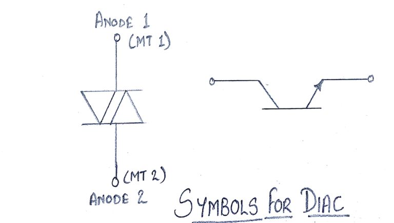
Circuit symbol
The DIAC circuit symbol is generated from the two triangles held between two lines as shown below. In some way this demonstrates the structure of the device which can be considered also as two junctions.
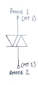
The two terminals of the device are normally designated either Anode 1 and Anode 2 or Main Terminals 1 and 2, i.e. MT1 and MT2.
DIAC applications
Typically the DIAC is placed in series with the gate of a TRIAC. DIACs are often used in conjunction with TRIACs because these devices do not fire symmetrically as a result of slight differences between the two halves of the device. This results in harmonics being generated, and the less symmetrical the device fires, the greater the level of harmonics produced. It is generally undesirable to have high levels of harmonics in a power system.
To help in overcoming this problem, a DIAC is often placed in series with the gate. This device helps make the switching more even for both halves of the cycle. This results from the fact that its switching characteristic is far more even than that of the TRIAC. Since the DIAC prevents any gate current flowing until the trigger voltage has reached a certain voltage in either direction, this makes the firing point of the TRIAC more even in both directions.