JK-F/F and T-F/F
Master Slave JK Flip Flop
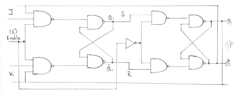
Master slave JK FF is a cascade of two S-R FF with feedback from the output of second to input of first. Master is a positive level triggered. But due to the presence of the inverter in the clock line, the slave will respond to the negative level. Hence when the clock = 1 (positive level) the master is active and the slave is inactive. Whereas when clock = 0 (low level) the slave is active and master is inactive.
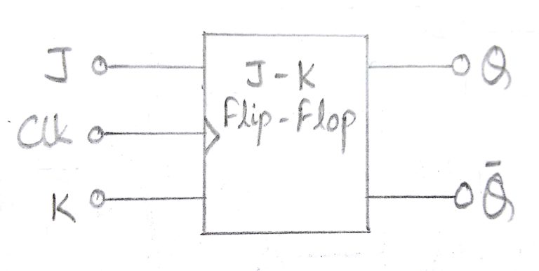
Block Diagram :
Circuit Diagram :
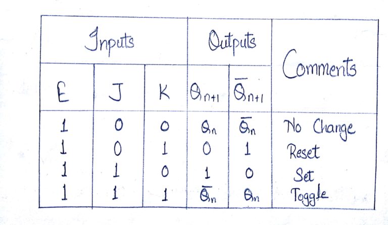
Truth Table :
Operation
| S.N. | Condition | Operation |
|---|---|---|
| 1 | J = K = 0 (No change) | When clock = 0, the slave becomes active and master is inactive. But since the S and R inputs have not changed, the slave outputs will also remain unchanged. Therefore outputs will not change if J = K =0. |
| 2 | J = 0 and K = 1 (Reset) | Clock = 1 − Master active, slave inactive. Therefore outputs of the master become Q1 = 0 and Q1 bar = 1. That means S = 0 and R =1. Clock = 0 − Slave active, master inactive. Therefore outputs of the slave become Q = 0 and Q bar = 1. Again clock = 1 − Master active, slave inactive. Therefore even with the changed outputs Q = 0 and Q bar = 1 fed back to master, its output will be Q1 = 0 and Q1 bar = 1. That means S = 0 and R = 1. Hence with clock = 0 and slave becoming active the outputs of slave will remain Q = 0 and Q bar = 1. Thus we get a stable output from the Master slave. |
| 3 | J = 1 and K = 0 (Set) | Clock = 1 − Master active, slave inactive. Therefore outputs of the master become Q1 = 1 and Q1 bar = 0. That means S = 1 and R =0. Clock = 0 − Slave active, master inactive. Therefore outputs of the slave become Q = 1 and Q bar = 0. Again clock = 1 − then it can be shown that the outputs of the slave are stabilized to Q = 1 and Q bar = 0. |
| 4 | J = K = 1 (Toggle) | Clock = 1 − Master active, slave inactive. Outputs of master will toggle. So S and R also will be inverted. Clock = 0 − Slave active, master inactive. Outputs of slave will toggle. These changed output are returned back to the master inputs. But since clock = 0, the master is still inactive. So it does not respond to these changed outputs. This avoids the multiple toggling which leads to the race around condition. The master slave flip flop will avoid the race around condition. |
Toggle Flip Flop / T Flip Flop
Toggle flip flop is basically a JK flip flop with J and K terminals permanently connected together. It has only input denoted by T as shown in the Symbol Diagram. The symbol for positive edge triggered T flip flop is shown in the Block Diagram.
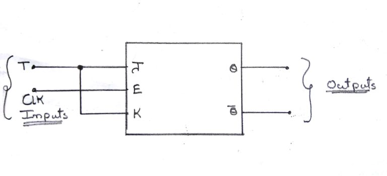
Symbol Diagram :
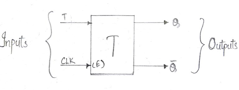
Toggle flip flop is basically a JK flip flop with J and K terminals permanently connected together. It has only input denoted by T as shown in the Symbol Diagram. The symbol for positive edge triggered T flip flop is shown in the Block Diagram.
Block Diagram :
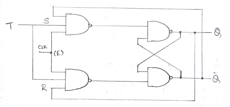
Circuit Diagram :
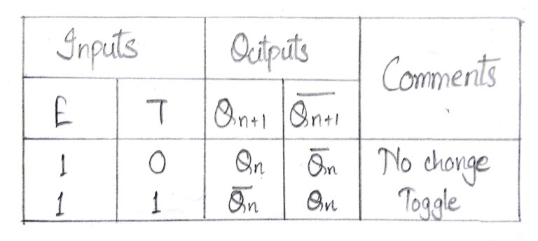
Truth Table :
Operation
S.N. Condition Operation 1 T = 0, J = K = 0 The output Q and Q bar won’t change 2 T = 1, J = K = 1 Output will toggle corresponding to every leading edge of clock signal.