Line Follower Robot
A Line Follower Robot, as the name suggests, is an Auto Guided Vehicle, which follow a visual line embedded on the floor. Usually, the visual line is the path which is followed by the line follower robot and it will be a black line on a white surface but the other way (i.e. white line on a black surface) is also possible. Line followers are one of the most prominent kinds of Robo cars. The technology now allows you to build a line follower in just under 10 minutes if you have the parts for it. So enjoy building this quick and easy line follower.
The line follower basically has two IR sensor these are embedded on the chassis such that it senses the line on both the side (Left and Right side in the front ) and passes the signal to microcontroller which accordingly drives the robo car. Let’s assume if the car senses the line in left it turns the car to the left and if the line is sensed to the right the mirco controller turns the car right.
We have selected this project so that the students can understand how the IR module works and how it can be interfaced with Arduino uno.
Pre-requisites:
First download Arduino IDE from this website https://www.arduino.cc/en/main/software
Component List :
1. Arduino Uno R3
2. Arduino Cable
3. IR Modules
4. Jumper Wires
5. Breadboard
6. DC motors
7. Chassis
8. Tyres
9. L293D motor driver IC
Connections :
Make the connections according to the Circuit Diagram
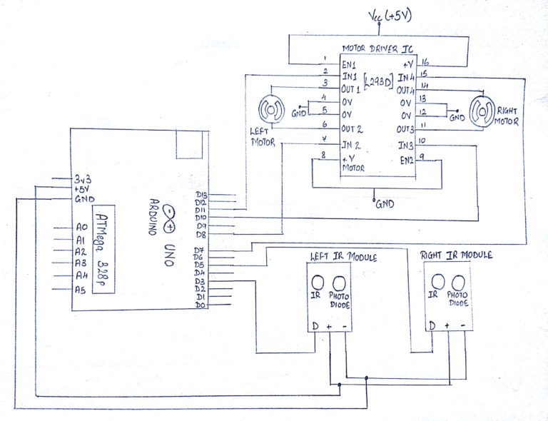
Steps For Connections:
Short the pins 1,8,9 and 16 of the Motor Driver IC and the Vcc pins of the IR modules to the Vcc(+5V) pin of the Arduino.
Short the pins 4,5,12, and 13 of the Motor Driver IC and the GND pins of the IR modules to the GND pin of the Arduino.
NOTE: It is recommended to connect 12V supply to the pins 8 and 16 of the Motor for better utilization of the RPM of a motor. Here, we have connected those 2 pins to 5V. It still works but your motor will work on lower RPM than provided by the manufacturer. It results slow speed.
For Right IR Module:
Connect the Data (D) pin to the digital pin – ‘5’ of the Arduino Uno.
For Left IR Module:
Connect the Data (D) pin to the digital pin – ‘3’ of the Arduino Uno.
For Motor Driver IC:
1. Connect the pin 2 of the Motor Driver IC to the digital pin 11 of the Arduino Uno.
2. Connect the pin 7 of the Motor Driver IC to the digital pin 8 of the Arduino Uno.
3. Connect the pin 10 of the Motor Driver IC to the digital pin 10 of the Arduino Uno.
4. Connect the pin 15 of the Motor Driver IC to the digital pin 7 of the Arduino Uno.
5. Connect the pin 3 of the Motor Driver IC to the 1st pin of the Left Motor.
6. Connect the pin 6 of the Motor Driver IC to the 2nd pin of the Left Motor.
7. Connect the pin 11 of the Motor Driver IC to the 2nd pin of the Right Motor.
8. Connect the pin 14 of the Motor Driver IC to the 1st pin of the Right Motor.
About Code:
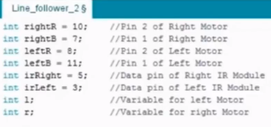
Declare the variables used to indicate the arduino pins to be connected to the pins of IR modules (Data).
Declare the variables used to indicate the arduino pins to be connected to the pins of the Motors.
Declare two variables ‘l’ and ‘r’ which would store the value given by the Data pin of both the IRs (Left and Right).
void setup
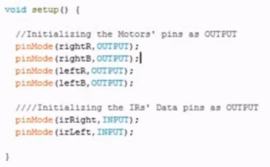
Define the Pin Mode as “INPUT” of the IR module data pin of both the side i.e. Left and Right to which the controller will accept, process and provide an output.
Define the Pin Mode as “OUTPUT” of the motor pins as the microcontroller would provide the desired output to the motor which in turn will control the car.
void loop
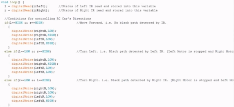
Read the data of the IR module and store it in defined variables.
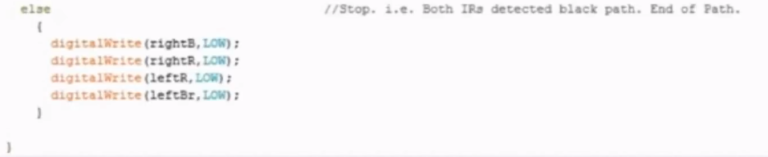
4 loops are made which holds the conditions considering the values of IR module of both the sides and according to the INPUT of the IR Module to the Arduino, the OUTPUT to the motor driver IC is given.
Thus, as the IR module will give certain signals while moving in any direction, that particular condition will be satisfied and the Signal changes present in that condition will be executed enabling the car to move in that direction.
Steps for Compiling Program:
1. Click on ‘Sketch’ on Menu bar.
2. Select ‘Verify/Compile’.
(or)
Press Ctrl + R
(or)
Click on the first button just below the menu bar. (Button with a tick)
Steps for Uploading Program:
1. Click on ‘Tools’ on the Menu Bar.
2. Go to ‘Board’ and select whichever Arduino you are using. Here, Arduino/Genuino Uno.
3. Go to ‘Port’ and select the COM Port in which you have connected your Arduino Uno. You can check out your COM Port by going to Device Manager>PORTS(COM & LPT)
4. Go to Programmer and select ‘AVRISP’.
5. Now click on ‘Sketch’ on Menu Bar.
6. Select Upload.
(or)
Press Ctrl + U
(or)
Click on the button next to the ‘verify/compile’ button below the Menu Bar. (Button with a right arrow).
If you are using an USBasp cable instead of Arduino Cable, then Choose USBasp in the Programmer options.
And then go to ‘Sketch’ and select ‘Upload using Programmer’ (or) press Ctrl+Shift+U.
Alternative
Any Colour Sensor can be used.