Passive High Filter
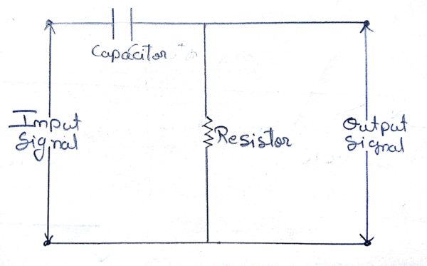
The Simple High Pass Filter can be designed by using a capacitor and a resistor is series. The Design is slightly different from the low pass filter i.e. the location of the capacitor and resistor.
The High Pass Filter as the name suggests the circuit allows only the frequency of the above the cut off frequency of the circuit and other all frequencies below the cut off frequency are rejected.
In this type of filter arrangement the input signal is applied to the series combination i.e. the resistor and capacitor are connected in series but the output signal is taken across the resistor only.
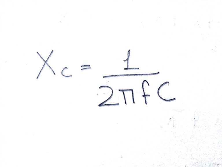
The formula above is for calculating the reactance of the capacitor with respect to frequency of the signal i.e. given to it. Where Xc is the reactance of the capacitor and the Term F represents the frequency of the signal given as input to the capacitor and C is the capacitance of the capacitor.
The reactance provided by the capacitor changes in accordance with the frequency of the signal. As shown in the capacitors reactance formula the reactance of the capacitor increases when the frequency of the signal is low due to which the low frequency signal is seen at the across the capacitor i.e. the low frequency signals are blocked at the input itself . While the capacitor provides very low reactance to the high frequency signals due to which the high frequency signals pass through the capacitor to the resistor i.e. .The signal can be seen across the resistor from where the output is taken .So Low Frequency won’t appear across the resistor i.e. from where the output is taken .
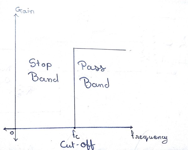
The above figure Shows the ideal output of the High pass filter. The Output shown above is not possible to achieve
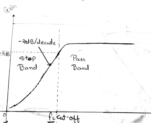
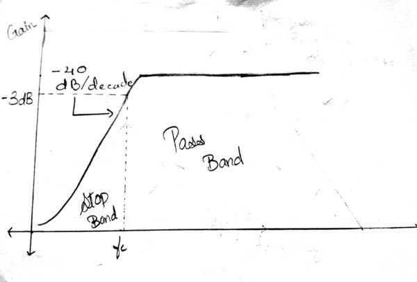
The practical output of the High pass filter is shown. From this we can see that the frequencies above the cut-off frequency fc the frequency are allowed to pass and the band allowed to pass is known as pass band while the others are attenuated the band which is attenuated is known as stop band.
It’s a first order High pass filter due to which the attenuation of the unwanted signal is at 20 db per decade i.e. attenuation is 20 dB per 10 hz.
Second Order High Pass Filter
So now we have studied about the single-pole arrangement i.e. a High pass filter designed using single capacitor and single that gives us a roll-off slope of -20dB/decade attenuation of frequencies below the cut-off point.
However, sometimes in filter circuits this -20dB/decade angle of the slope may not be enough to remove an unwanted signal then two stages of filtering can be used as shown.
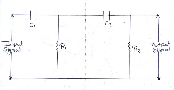
In the second order circuit that uses two passive first-order high pass filters connected together to form a Second-order filter network. Therefore we can see that a first-order high pass filter can be converted into a second-order type by simply adding an additional RC network to it and the more RC stages we add the higher becomes the order of the filter.
The Order of the filter increases as the number of First order high pass filters are connected together in series. The Order of the filter is dependent on the number of the filter connected in series. If Two first order are connected together than the Order of the filter is second and has the Roll-off of the attenuation of -40db/decade. If Three first order are connected together than the Order of the filter is Third and has the Roll-off of the attenuation of -80db/decade.