Water Level Buzzer
Water tank overflow is a common problem which leads to the wastage of water. Though there are many solutions to it like ball valves which automatically stop the water flow once the tank gets full. But being an electronics enthusiast wouldn’t you like an electronic solution for it?
So here is a simple and handy DIY that will guide you to make a circuit which will detect the water level and will raise an alarm upon getting the water tank full or a preset level.
Here we are using the ultrasonic waves to detect the distance between the top level and the level of the water at the movement. The Ultrasonic sensor provides the micro controller with the time it took to reflect back and the calculations are made by the waves to reflect back and the distance is calculated. According to it the buzzer buuzes.
We have taken up this project so that the students can learn about Ultrasonic sensors and how they can be used for accurate measurements.
List Of Components:
1. Arduino Uno R3
2. Arduino Cable
3. Male to Male Jumpers
4. Buzzer
5. Ultrasonic Sensor HC SR-04
6. Breadboard
Steps For Connections:
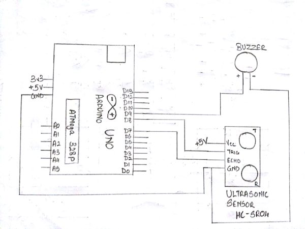
For Ultrasonic sensor(HC SR-04):
Connect the Vcc pin to the Vcc(+5V) of the Arduino.
Connect the GND pin to the GND of the Arduino.
Connect the trig pin to the digital pin – 8 of the Arduino.
Connect the echo pin to the digital pin – 7 of the Arduino.
For Buzzer:
Connect the positive terminal (the pin which is long), to the digital pin – 9 of the Arduino.
Connect the negative terminal (the pin which is short), to the GND of Arduino or short it with the GND pin of Ultrasonic sensor as shown in the Schematic.
About Code:
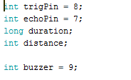
Declare the variables used to indicate the arduino pins to be connected to the pins of Ultrasonic Sensor (Trigger and echo).
Declare the variable used to indicate the arduino pin to be connected to the pin of the Buzzer.
Declare the variables to be used as a storing element.
void setup
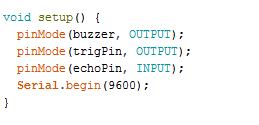
Define the Pin Mode as “INPUT” of the echo pin of Ultrasonic Sensor as it would give the values of the echo duration to which the controller will accept, process and provide an output.
Define the Pin Mode as “OUTPUT” of the trigger pin as the microcontroller would send pulses which would be detected by the Echo pin.
To check the distance between the object and the sensor, Serial Communication is used which would display the values on the Arduino’s Serial Monitor.
The baud rate is set to 9600 to start the serial communication.
-void loop:
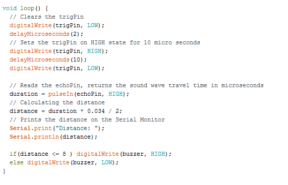
Trig pin requires 10 micro second pulse to transmit.
Now, the echo pin is checked for the amount of time it receives back the pulse transmitted by the trigger pin, indicating the detection of an object.
Distance is calcuted by using the general formula using time and speed of sound.
Here, Distance is measured in cm.
The value of Distance obtained is then displayed on the Serial Monitor using Serial.print
An if else loop is made to satisfy a condition to make the Buzzer Buzz.
Here, if the distance is less than 8 cm, the Buzzer will start buzzing else it would stop.
IMPROVISATION:
You can use a LCD Display to display the level of the water in terms of centimetres or any other unit. For this, A LCD Display is need to be interfaced with the Arduino and an initialization code is required. Relax, it isn’t that difficult as it sounds.
You can read about the various pins of LCD and try to do it on own.
If you are unable to do it, then watch our next video on Auto Parking Status Project where you’ll learn how to interface a LCD and what code is required to display.
Steps for Compiling Program:
1. Click on ‘Sketch’ on Menu bar.
2. Select ‘Verify/Compile’.
(or)
Press Ctrl + R
(or)
Click on the first button just below the menu bar. (Button with a tick)
Steps for Uploading Program:
1. Click on ‘Tools’ on the Menu Bar.
2. Go to ‘Board’ and select whichever Arduino you are using. Here, Arduino/Genuino Uno.
3. Go to ‘Port’ and select the COM Port in which you have connected your Arduino Uno. You can check out your COM Port by going to Device Manager>PORTS(COM & LPT)
4. Go to Programmer and select ‘AVRISP’.
5. Now click on ‘Sketch’ on Menu Bar.
6. Select Upload.
(or)
Press Ctrl + U
(or)
Click on the button next to the ‘verify/compile’ button below the Menu Bar. (Button with a right arrow).
If you are using an USBasp cable instead of Arduino Cable, then Choose USBasp in the Programmer options.
And then go to ‘Sketch’ and select ‘Upload using Programmer’ (or) press Ctrl+Shift+U.