RTC Interface with Arduino
A Real Time Clock module is basically a time tracking device which gives the current time and date. RTC module that comes with DS3231 IC have the provision to set alarms.
The first question that comes here is why we actually need a separate RTC for our Arduino Project when the Arduino itself has built-in timekeeper. Well the point is that the RTC module runs on a battery and can keep track of the time even if we reprogram the microcontroller or disconnect the main power.
So lets understand how this RTC works and how it is interfaced with the arduino using I2C communication protocol
Components required :
1. Arduino Uno R3
2. Arduino Cable
3. RTC DS1307
4. LCD Display
5. Male to male Jumper wires
6. Breadboard
Connections:
Refer the schematics for the connections.
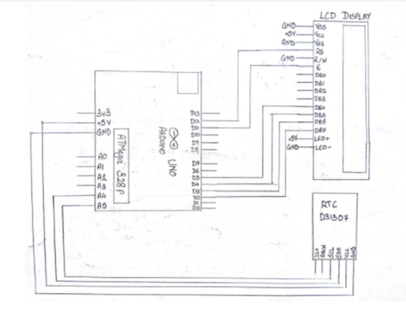
Steps For Connections:
Make separate common connections line for VCC and GND.
For RTC DS1307:
Connect the Vcc pin to the common Vcc line.
Connect the GND pin to the common GND line.
Connect the SDA pin to the analog pin – ‘A4’ of the Arduino.
Connect the SCL pin to the analog pin – ‘A5’ of the Arduino.
For LCD Display:
Connect the VSS pin to the common GND line.
Connect the VDD pin to the common Vcc line.
Connect the VEE pin to the common GND line.
Connect the RS pin to the digital pin – 12 of the Arduino.
Connect the RW pin to the common GND line.
Connect the E pin to the digital pin – 11 of the Arduino.
Connect the D4 pin to the digital pin – 5 of the Arduino.
Connect the D5 pin to the digital pin – 4 of the Arduino.
Connect the D6 pin to the digital pin – 3 of the Arduino.
Connect the D7 pin to the digital pin – 2 of the Arduino.
Connect the LED A(Anode, or LED+) pin to the common Vcc line.
Connect the LED K(Cathode, or LED-) pin to the common GND line.
Connect the two common Vcc and GND lines to the Vcc(+5V) and GND of the Arduino using two jumpers.
CODE:
Declaration
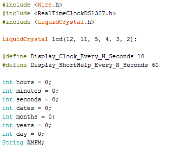
-Include the Wire.h library for I2C Communication.
-Include the RealTimeClockDS1307.h library for initialising RTC.
-Include the LiquidCrystal.h library for initialising the LCD.
-Declare the variables for each parameter of Time and initialise them to 0.
void setup
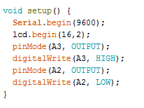
-Serial communication is initialised to baud rate 9600.
-LCD display is initialised by lcd.begin().
-Analog pins A2 and A3 are declared as Output and made low and high respectively, this can be used to power the RTC. Its optional as we are powering the RTC using the +5V and GND pin.
Void days:
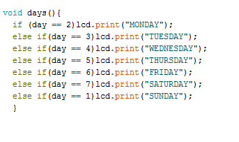
-This is a function which would check the value present in the ‘day’ variable and accordingly print the day name in words.
-void loop:
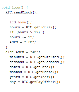
-RTC is initialised first using RTC.readClock() and the transmission is begin with the Slave device i.e. our RTC module. The register Pointers are reset.
-RTC is initialised first using RTC.readClock() and the transmission is begin with the Slave device i.e. our RTC module. The register Pointers are reset.
-All the variables declared above are now stored with the value previously present in the RTC using the function RTC.get…().
-To show the time in a 12hr format we can use the inbuilt function as well or use a if-else loop where we convert the 24hr time into 12hr time zone. Here, as you can see we have used an if-else loop.
-If you want to use the 24hr format just remove or comment the if-else loop used for conversion and also the lcd.print(AMPM) command.
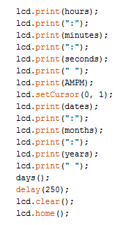
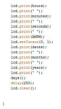
-Now, using lcd.print() function we display the time and date on the LCD.
-setCursor is used to point the cursor at the particular row and column.
After you upload the code you will get the time last stored in the RTC, if you haven’t used RTC yet then it will start from all 0s.
You can also find example codes after you install the library in the Arduino.
Steps for Compiling Program:
1. Click on ‘Sketch’ on Menu bar.
2. Select ‘Verify/Compile’.
(or)
Press Ctrl + R
(or)
Click on the first button just below the menu bar. (Button with a tick)
Steps for Uploading Program:
1. Click on ‘Tools’ on the Menu Bar.
2. Go to ‘Board’ and select whichever Arduino you are using. Here, Arduino/Genuino Uno.
3. Go to ‘Port’ and select the COM Port in which you have connected your Arduino Uno. You can check out your COM Port by going to Device Manager>PORTS(COM & LPT)
4. Go to Programmer and select ‘AVRISP’.
5. Now click on ‘Sketch’ on Menu Bar.
6. Select Upload.
(or)
Press Ctrl + U
(or)
Click on the button next to the ‘verify/compile’ button below the Menu Bar. (Button with a right arrow).
If you are using an USBasp cable instead of Arduino Cable, then Choose USBasp in the Programmer options.
And then go to ‘Sketch’ and select ‘Upload using Programmer’ (or) press Ctrl+Shift+U.